Suggested lengths of flexible tails:
coils 1 and 6 - 800 mm flex
coils 2 and 5 - 600 mm flex
coils 3 and 4 - 400 mm flex
• Cover the soldered joints with sleeving. Leave no bare copper showing.
• Label the tails with the coil number and the letter A or B.
A is for the start of the coil, B is for the finish. Do not mix them up.
Or use two colours: black flex for the starts and white for the finishes.
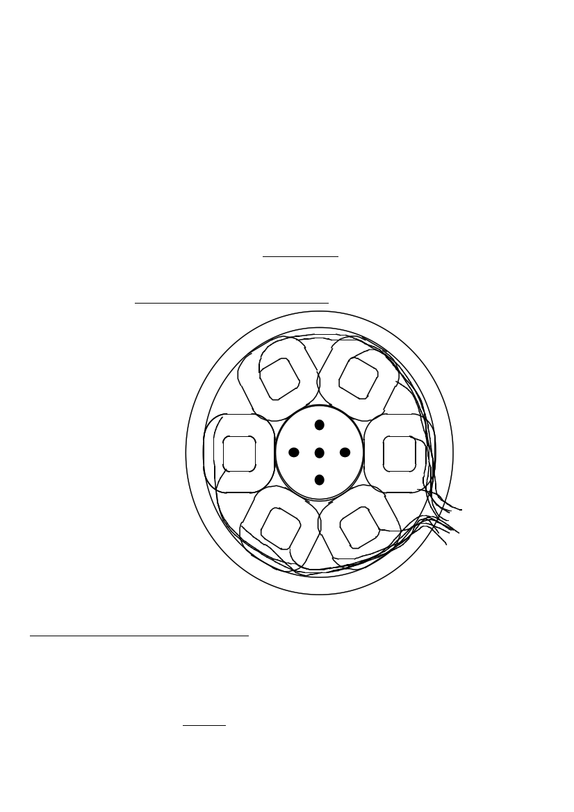
• Lay the coils out in the outer mould.
• Check that they will fit comfortably, and that the tails are long enough to remain
within the mould until the exit point between coils 3 and 4.
It is important to lay all the coils the same way up.
29. THE COILS IN THE MOULD
2
1
Holes shown black
3
6
5
4
Preparations for stator casting
The stator casting will contain:-
• six coils
• polyester resin and talcum powder (and perhaps pigment)
• fibreglass mat (CSM)
• four studs of 8mm x 100mm threaded rod
Also, be sure to have the moulds prepared properly. Sand them, seal them, polish
them. If PVA release agent can be got, then use it.
PMG manual
page 27
June 2001